Welcome to Power Wheels Wiring 101! Before you hurl yourself headfirst into any Power Wheels upgrade, you need to understand the electric system. Though it may seem intimidating, when it comes to wiring, Power Wheels is about as simple as it gets!
Bookmark this page to reference for your Power Wheels DIY projects. Being familiar with the wiring diagram of your Power Wheels can help you do many things. Repairing a wire, replacing the motors, upgrading the battery, and more are easier tasks when the wiring circuit is understood.
Remember that though it’s all under the same brand umbrella, the different models of cars may vary in their wiring depending on their design and functionality. This guide will provide the basic wiring diagram of the most common Power Wheels.
Component Definitions
Before we begin, let’s take a moment to define all the components we will be discussing in this guide. Included below are photos of stock parts so you can easily reference them to your Power Wheels model. Some items may vary (like the inclusion of a hi/lo switch or not), but each part will look at least similar to that pictured!
Battery: The Power Wheels vehicle receives its power from the battery. Within this container, chemical energy is transformed into electric energy and will travel via the wires of the electric circuits described in this guide.
See the below example of a 6V Power Wheels battery with wires:
No products found.
Motor: mechanism for transmitting battery power into spinning the wheels. It is powered by electricity supplied from the battery, which is transmitted into motive power.
See the below example of a gearbox and motor assembly. The motor is the metal cylinder with the wires attached.
No products found.
Throttle switch: a three-pin switch connection, usually connected to the accelerator pedal. In other words, your GO pedal!
See the below example of a plunger accelerator (the pedal sits on top to depress the plunger):
No products found.
Resistor: device for softening the brake, connected to the negative terminal of the battery. Instead of a braking pedal, Power Wheels utilizes this resistor to short the motor when the accelerator is released, thus slowing or stopping the vehicle.
See the below example of a resistor device:
No products found.
Shifter Assembly:
The Power Wheels shifter assembly encompasses both of the following six-pin switches or just the Forward/reverse switch in some models:
- Forward/Reverse (toggle) switch: a six-pin switch used to reverse the polarity of the motor, thus enabling reverse rotation of the wheels.
- Hi/Low switch: a six-pin switch used to change the speed limits of the car.
See the below example of the shifter assembly with the two six-pin switches:
No products found.
Fuse: small device connected to the positive terminal of the battery that provides a break in circuit to protect the battery from overloading.
See the below example of a basic inline fuse:
No products found.
Parallel wiring: Allows the full battery voltage to provide power to the motors.
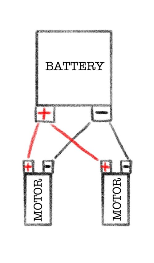
Creates an X-shaped wiring. Circuits wired in parallel have the positive terminal of the battery connected to the positive terminal of the motors and the negative terminal of the battery connected to the negative terminals of the motors.
Series wiring: Allows the battery voltage to be divided between the motors.

Creates a circular loop of wiring. The battery’s positive terminal is connected to the positive terminal of one motor and then the positive terminal of the second motor. The negative terminal of the battery is connected to the negative terminal of the second motor and then the negative terminal of the first motor.
How a Power Wheels Car Works
You will find the battery on your Power Wheels either under the hood or in the car’s rear compartment. The battery transfers power via wiring to the car’s motors, which transmit this energy from power into rotation. The motors are connected to gearboxes that accept the spinning power of the motor and transfer it to the wheels to create acceleration and deceleration.
Within this electrical circuit is a toggle (a forward/reverse switch) switch, which allows the wires to reverse their polarity and cause reverse spinning on the wheels, to drive in reverse.
Some cars also feature a Hi/Low switch, allowing the car to go faster or slower.
From this basic understanding, you can move on to studying the wiring diagrams below to further explore how a Power Wheels car functions.
Wiring Diagram
The following diagrams represent various Power Wheels model wiring setups. From the basic single motor 6v to the standard dual-motor models, you can see that the wiring stays relatively the same while accommodating a few extra features.
Power Wheels with a Single Motor
The single motor vehicles are little 6V battery cars designed by Power Wheels and are your starter versions for tiny tots. These cars can go forwards or backward and do not usually feature hi/low switches. They are wired in parallel.
A car of this design will include the following wiring components:
- One 6V battery
- One 6V motor
- Throttle switch
- Forward/Reverse (toggle) switch
- Fuse
- Resistor
From the battery’s positive terminal, the inline fuse is connected, then attached to the top pin of the three-pin throttle.
The bottom pin of the throttle connects to the resistor, which connects to the battery’s negative terminal.
Next up is the toggle switch! The center-left pin connects to the final open ping on the throttle, which is the middle pin. The center-right pin connects to the battery’s negative terminal via the resistor. The bottom left pin attaches to the positive terminal of the motor. The bottom right pin attaches to the negative terminal of the battery.
Now, you will also notice the yellow lines on the toggle switch in the diagram below. These represent the crossed wires – top right to bottom left and top left to bottom right. At this point, these loops reverse the polarity to the motor, allowing the wheels to spin backward and move the car in reverse.

This setup is considered parallel as the battery ultimately links its positive and negative terminals to the single motors terminals. Once we add a second motor, as described in the next section, we move to a series setup.
Power Wheels with Two Motors
Most Power Wheels cars include two motors and are wired in series. This category includes the ever-popular Jeeps that come in many varieties of branding and styles. The main distinction in this wiring diagram is the inclusion of the High/Low switch, additional motor, and wiring in series. Refer to the diagram below!
A car of this design will include the following wiring components:
- One 12V or 18V battery
- Two motors
- Throttle switch
- Forward/Reverse (toggle) switch
- High/Low switch
- Fuse
- Resistor
The wiring is quite similar here until you pass the toggle switch. The bottom right pin of the toggle switch is connected to the right motor’s negative terminal, and the bottom left pin is connected to the negative terminal of the left motor.
Those crossed yellow wires (which will not necessarily be yellow on your actual Power Wheels model, but are for the sake of this diagram) also include a connection to the hi/Lo switch. The bottom left of the toggle connects to the top left of the hi/lo, and the bottom right of the toggle connects to the top right of the hi/lo.
The hi/lo switch also connects directly to the motors. The center-left pin connects to the right motor’s positive terminal, and the center-right pin connects to the positive terminal of the left motor. The bottom two pins of the hi/lo switch are connected to each other in series.
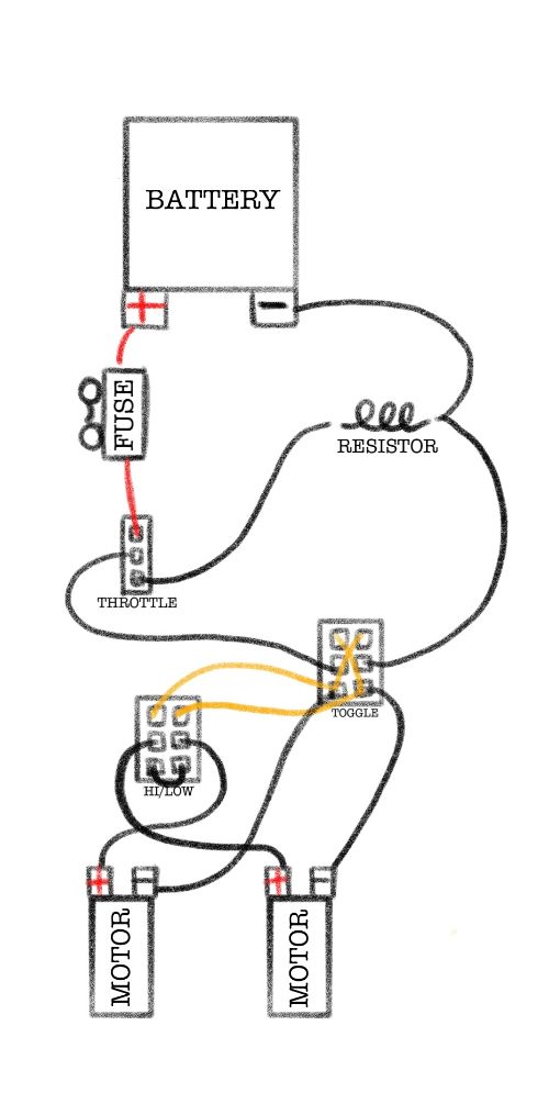
The above setup is wired in series – do you notice how the positive terminals of the two motors connect to each other via the hi/lo switch? Whereas the negative terminals of the motors are routed towards the battery, creating a loop-like circuit, versus the direct connection seen in the parallel wiring.
Final Comments
Congratulations! You’ve graduated from Power Wheels Wiring 101! Up next, can you tackle a Power Wheels upgrade DIY? Check out one of our many articles on upgrading various aspects of your child’s ride-on car, from the battery to the motor to the tires! This diagram will also come in handy when troubleshooting your electric riding vehicle.
With this handy wiring guide, you’ll be ready to plug into any project, whether a simple repair or a sweet upgrade. You may even consider printing out the diagram related to your Power Wheels model to keep for a quick reference. And remember, when in doubt, seek professional help!